
What Is a Checking Fixture? Purpose, Design and Manufacturing Applications
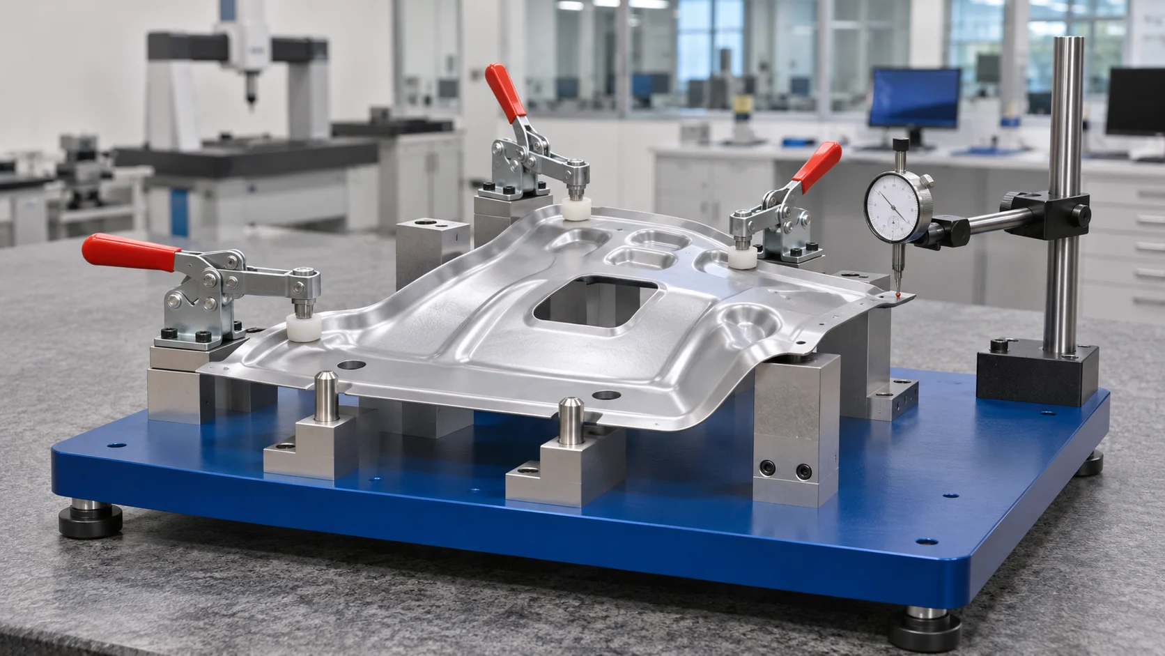
A checking fixture is a dedicated inspection tool used to verify important features of a manufactured component. It holds or locates the part in a defined position, allowing operators to check surfaces, edges, holes and other characteristics consistently.
Checking fixtures are widely used for sheet metal and plastic components, particularly where complex shapes make inspection difficult with ordinary measuring tools alone. They provide a practical way to assess selected features without creating a new measurement setup for every component.
Their effectiveness depends on correct positioning, suitable support and a clearly defined inspection procedure. A fixture must provide reliable information about the part rather than simply make it easier to hold.
Why Are Checking Fixtures Used?
A component can appear correct while still having dimensional differences that affect assembly.
A mounting hole may be slightly out of position. A flange may not follow its intended profile. A plastic cover may show distortion around its attachment points. These variations can create assembly difficulties, uneven gaps or poor alignment with neighbouring components.
A checking fixture helps operators inspect these important areas in a repeatable way.
Depending on its design, it can support checks of:
- Hole and slot positions.
- Trimmed edges and cut lines.
- Surface profiles.
- Flanges and bent features.
- Gaps at specified inspection points.
- Features that influence assembly fit.
Each fixture has a defined inspection scope. Passing its checks does not automatically confirm that every dimension on the component drawing is acceptable.
How Does a Checking Fixture Work?
The inspection process starts by placing the component onto its designated locating and support elements.
Reference pins, contact surfaces and supports establish the required position. Where clamping is necessary, the operator closes the clamps in the specified sequence.
Once the component is correctly seated, the operator checks the required features using the fixture’s checking elements and any additional measuring instruments.
Some checks provide a straightforward pass-or-fail result. Others record a measured deviation.
For example, a checking pin may assess a hole against a defined checking condition. A feeler gauge may check a specified gap, while a dial indicator may measure variation at a selected surface point.
The inspection instructions should explain what each check evaluates and how its result should be recorded.
Main Components of a Checking Fixture
Base Structure
The base carries the locating, support, clamping and checking elements.
It needs sufficient stability for the intended inspection conditions. Its construction also depends on the size of the component, handling requirements and the environment in which the fixture will be used.
Locating Pins and Reference Elements
Locating elements establish the position of the component.
They may engage with designated holes or contact selected reference surfaces. Their arrangement should follow the inspection requirements and the component’s reference system.
Using convenient but unsuitable locating features can produce misleading results. The relationship between the part and the fixture must represent the intended inspection setup.
Supports
Supports provide contact beneath or around selected areas of the component.
Their position is especially important for thin sheet metal and flexible plastic parts. Poorly positioned supports can allow movement, while unnecessary contact can change the component’s shape during inspection.
Clamps
Clamps hold the component in its specified inspection condition.
Clamp position, force and closing sequence all require consideration. Excessive force can deform a flexible component and influence the result.
The operator should never need to force a component into place simply to make it pass a check.
Checking Elements
Checking elements provide the means to inspect selected features.
They can include checking pins, reference blocks, profile sections, gap-checking surfaces and mounting points for measuring instruments.
Clear labels help operators identify the correct checking locations and follow a consistent procedure.
Why Correct Positioning Matters
Correct positioning is fundamental to meaningful inspection.
Before closing the clamps, the operator should confirm that the component is seated against its intended locating features. Reference pins must be engaged correctly, and the relevant contact surfaces should be clean.
A small piece of debris beneath a support can change the position of the component. An incorrectly seated locating pin can affect several inspection points at once.
These problems can make an acceptable component appear defective or conceal an actual manufacturing variation.
The loading procedure should therefore be treated as part of the inspection method.
Why the Clamping Sequence Is Important
Thin or flexible components can change shape as clamps are applied.
Closing the clamps in different orders may produce different seating conditions. This is why the prescribed sequence should be clearly identified and followed consistently.
The required inspection state must also be defined. A component may need to be checked in a relatively free condition or in a constrained condition representing its installed position.
These conditions answer different inspection questions. The fixture design and operating instructions should make the intended condition clear.
Applications in Automotive Manufacturing
Checking fixtures are particularly useful in automotive production, where many individual components must fit together accurately.
Typical applications include body panels, brackets, reinforcements, interior trim and plastic covers.
Consider a sheet metal bracket with mounting holes and a formed flange. Its checking fixture may locate the bracket through designated reference features, support it at selected points and provide access to inspect the holes and flange profile.
If the bracket fails a check, the manufacturing team can investigate the affected feature and compare it with production conditions.
The fixture helps identify where a deviation appears. Further investigation determines whether the cause comes from forming, trimming, material variation or the inspection setup itself.
Supporting Die Tryout and Production Adjustment
When a forming die is first installed in a press, achieving the required component geometry may involve several rounds of trial production and adjustment.
Checking fixtures provide a consistent way to assess the resulting parts.
Repeated checks can show whether a particular flange, edge or surface remains outside its required condition. This helps the team focus its investigation and compare the results of successive adjustments.
However, a checking fixture does not automatically identify the correct tool modification.
Its results need to be interpreted alongside the forming process, material behaviour and other dimensional information. The fixture provides evidence that supports the engineering decision.
Checking Fixtures and CMM Inspection
A checking fixture and a coordinate measuring machine, or CMM, can support different parts of the same quality process.
A dedicated checking fixture provides convenient access to selected production checks. A CMM collects dimensional information through a planned measurement process.
Some fixtures are designed specifically to position components for CMM inspection. Their main purpose is to hold the part securely while preserving access to the required features.
The appropriate approach depends on the component, inspection requirements, production volume and level of dimensional information needed.
What Makes a Good Checking Fixture?
A good checking fixture should be easy to load correctly and practical to use repeatedly.
Its design should provide:
- A locating arrangement that reflects the inspection requirements.
- Suitable support for the component.
- Controlled clamping where required.
- Clear access to checking points.
- Identifiable and maintainable checking elements.
- Instructions covering loading, inspection and result recording.
- Clear identification of the applicable part and revision.
The fixture itself also requires verification and maintenance.
Worn pins, loose elements, contamination and accidental damage can affect its performance. These conditions should be addressed before inspection results are used to make production decisions.
Common Inspection Mistakes
Common problems include incomplete seating, incorrect clamp order and dirt on locating surfaces.
Other issues arise when operators use excessive force, select the wrong checking pin or follow instructions for an earlier component revision.
Another mistake is assuming that a component is fully acceptable simply because it fits onto the fixture.
The fixture only evaluates the features covered by its approved checking method. Additional measurements may still be necessary.
Engineering Perspective
Checking fixtures create a practical connection between component design, manufacturing and dimensional quality control.
Their value comes from a defined and repeatable inspection setup. Correct locating points, suitable supports, controlled clamping and clear instructions all contribute to useful results.
For complex sheet metal and plastic components, a well-designed checking fixture can simplify routine inspection, reveal manufacturing variation and support production adjustments.
The objective is to give the manufacturing team reliable information about the features that matter to the component’s function and assembly.
Report an image

 MEMBERS · ONE ENGINEERING COMMUNITY
Discussion
0 CommentsShare your thoughts and engineering insights with the community.
Sign in to join the discussion.
Join the discussionNo comments yet. Be the first to share your thoughts.