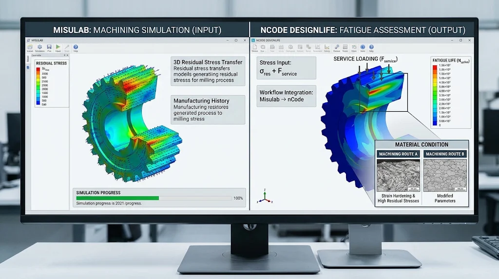
Misutech and HBK have connected machining simulation with fatigue assessment through an interface between Misulab and nCode DesignLife. The reported integration transfers three-dimensional residual stress information from the manufacturing simulation into the fatigue workflow alongside service loading. For component designers, the development addresses an important gap between specifying a finished shape and understanding the material condition created while that shape is manufactured. Machining can influence durability even when the resulting geometry satisfies its drawing.
The surface has a manufacturing history
A conventional geometric inspection establishes dimensions and form, but it does not describe every change introduced near a machined surface. Cutting involves local deformation and heating. The source identifies residual stresses, strain hardening and microstructural changes among the effects that can influence subsequent fatigue behaviour. These characteristics make the manufacturing route relevant to a component assessment that might otherwise focus mainly on nominal material properties and service loads.
For an engineer reviewing a process change, this creates a practical distinction. Two components can share the same CAD definition while reaching service with different local material states. A change in tooling or machining conditions may therefore require consideration beyond the expected cycle time and surface finish. The appropriate assessment depends on the part’s loading and the location of features that are important to its durability.
Connecting the models coherently
The interface described in the announcement is useful because it moves manufacturing information into the environment where fatigue is evaluated. That transfer needs a consistent interpretation of position and direction. A residual stress field belongs to a particular geometry and manufacturing state; the receiving analysis must associate it with the corresponding component representation. Engineers should establish how the mapped information is checked before using the combined result to compare alternatives.
Mesh differences and local geometric detail can complicate that handover. The area most sensitive to fatigue may also contain a small radius or another feature whose representation differs between models. A successful file transfer does not establish that every important local effect has been retained. Reviewing the transferred field at critical regions is therefore part of developing confidence in the workflow.
Compare machining strategies against a common question
The companies describe evaluating alternative cutting strategies and tooling changes through the connected software. A useful comparison should keep the component requirements and service loading consistent while identifying the manufacturing variables being changed. Otherwise, an apparent improvement may arise from different assumptions rather than a more suitable machining route. The study should record both the expected manufacturing benefit and the predicted durability consequence.
The service-load definition remains important even when the manufacturing model becomes more detailed. If the operating conditions are poorly represented, additional detail in the initial stress state cannot resolve that uncertainty. Engineers should identify which inputs have the strongest influence on the decision and direct verification effort accordingly. This helps prevent a sophisticated model from obscuring a basic weakness in the assessment assumptions.
Establish an appropriate verification route
The announcement presents the integration as a way to reduce dependence on extensive physical trials. That is a development objective rather than proof that testing becomes unnecessary. Representative measurements and fatigue evidence remain useful for understanding how accurately the connected method describes the intended material and process. The verification programme should match the significance of the design decision being supported.
For The CAD Verse audience, the engineering opportunity is to make process selection part of durability reasoning earlier in development. Misulab and DesignLife address different stages of that reasoning, and their connection can support more informative comparisons. The strongest application will preserve traceability between the machining definition, transferred material state and service assessment, allowing a team to explain why a proposed production change remains consistent with the component’s functional requirements.
Source — develop3d.com. Source publication date 2026-03-05. Engineering analysis: The CAD Verse.