How Intent-Driven Design, AI-Assisted Feature Recognition, and Connected Engineering Workflows Are Transforming Product Development
Parametric modeling has been one of the fundamental technologies behind modern computer-aided design (CAD) for decades. By defining dimensions, geometric relationships, constraints, and feature dependencies, engineers can create digital models that adapt to changing design requirements without rebuilding geometry from scratch.
However, the expectations placed on modern CAD software are evolving.
Today, engineering teams need more than tools for creating accurate 3D geometry. They need intelligent design environments that preserve engineering intent, simplify product modifications, support collaboration, and connect design activities with manufacturing and simulation.
Autodesk Fusion is developing in this direction through its combination of parametric modeling, direct editing, design automation, and AI-assisted engineering capabilities.
Recent developments in 2026, particularly the introduction of Intent-Driven Design workflows and the AI-powered AutoTimeline feature, demonstrate how Autodesk is approaching the next stage of digital product development.
1. Understanding Parametric Modeling in Modern CAD
Parametric modeling is a design methodology in which geometry is controlled by dimensions, parameters, constraints, and relationships between individual features.
Instead of creating a model as a collection of independent surfaces and solids, engineers build a structured design in which modifications can propagate through the model.
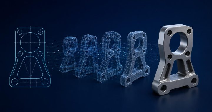
For example, consider a mechanical mounting bracket containing several holes, ribs, and mounting surfaces.
In a conventional geometry-driven workflow, changing the distance between mounting holes may require several manual modifications.
In a parametric workflow, the designer can define relationships between those holes, connect them to named parameters, and allow the model to update when the relevant dimensions change.
This approach provides several advantages:
- Faster design modifications.
- More consistent design variations.
- Better control over dimensional relationships.
- Reduced repetitive modelling work.
- Improved communication between engineering teams.
- Easier adaptation to changing product requirements.
The real value of parametric modeling is therefore not simply the ability to change dimensions. It is the ability to preserve the logic behind a design.
2. Autodesk Fusion and the Importance of Design Intent
One of Autodesk Fusion’s important development directions is Intent-Driven Design.
Design intent describes the engineering logic that determines how a model should behave when dimensions, features, or product requirements change.
Consider a simple example: a component has four mounting holes arranged symmetrically around its centre.
A purely geometry-based model may contain four holes positioned at fixed coordinates.
An intent-driven model defines their symmetry and relationships explicitly. If the component dimensions change, the holes remain symmetrically positioned without requiring the designer to reposition each one manually.
Autodesk Fusion supports this approach through several connected capabilities:
Parametric Feature History
Fusion records design operations in a timeline. Sketches, extrusions, fillets, patterns, and other modelling operations can be revisited and modified.
Sketch Constraints
Geometric constraints define relationships such as symmetry, equality, concentricity, tangency, and perpendicularity.
User Parameters
Engineers can define named variables such as wall thickness, mounting-hole diameter, clearance, and component length.
Associative Relationships
Features can reference other design elements, allowing changes to propagate through dependent geometry.
Assembly Joints
Mechanical relationships such as revolute, slider, and cylindrical joints describe how components are intended to move relative to one another.
Together, these capabilities help create models that are easier to understand, modify, and reuse.
Importantly, design intent is not a single software command. It is a modelling strategy supported by multiple interconnected tools.
3. Parametric Modeling and Direct Modeling: Two Complementary Approaches
Not every engineering project starts with a clean, editable parametric model.
In real product development environments, engineers frequently work with imported STEP files, supplier models, legacy geometry, customer-provided data, and components created in different CAD systems.
These models may contain accurate geometry but lack the original feature history and design relationships.
Autodesk Fusion supports two primary modelling approaches:
Parametric Modeling
In this mode, design operations are recorded in the timeline. Features maintain relationships with previous operations, allowing engineers to revisit and modify the construction history.
Direct Modeling
Direct modeling allows users to modify geometry without maintaining a parametric feature history. It can be useful for rapid design changes, imported models, and situations where the original construction logic is unavailable.
The ability to work with both approaches is important because engineering teams rarely operate within a single software environment.
For example, a supplier may provide a STEP model of an existing component. An engineer can modify its geometry directly or use available feature-recognition tools to develop a more structured model.
This flexibility helps bridge the gap between traditional CAD design and modern multi-platform engineering workflows.
4. AI-Powered AutoTimeline: Turning Imported Geometry into Parametric Models
One of the most interesting developments in Autodesk Fusion’s October 2026 update is AutoTimeline.
Working with imported CAD geometry can be challenging because neutral-format files such as STEP often preserve geometric information without reproducing the original parametric feature history.
This means that engineers may receive a fully accurate solid model but still need to recreate sketches, holes, extrusions, and other features manually before making substantial design changes.
AutoTimeline aims to reduce this effort.
The feature uses AI-assisted feature reconstruction to identify design features within imported geometry and recreate them in the Fusion timeline.
The resulting model becomes an editable parametric Fusion design that engineers can continue modifying with familiar modelling tools.
Potential benefits include:
- Reducing manual reconstruction work.
- Improving the reuse of imported CAD geometry.
- Supporting reverse engineering workflows.
- Making supplier models easier to adapt.
- Accelerating modifications to legacy components.
- Improving continuity between different CAD environments.
An Important Technical Distinction
AutoTimeline should not be interpreted as a universal conversion tool that automatically recovers every original design decision from any imported CAD file.
The original sketches, constraints, feature names, and engineering intent may not always be recoverable from neutral geometry.
The feature is intended to reconstruct editable design features, not necessarily reproduce the exact original modelling history created in another CAD application.
As of October 2026, Autodesk identifies AutoTimeline as a Technical Preview available to Fusion Design Extension users.
Its long-term engineering value will depend on recognition accuracy, supported geometry types, model complexity, and the amount of manual validation required.
Nevertheless, it represents an important step towards reducing the gap between imported geometry and editable parametric design.
5. More Intelligent Sketching and Feature Management
Sketches are the foundation of many parametric CAD models.
A sketch may define the geometry of an extrusion, revolve, sweep, loft, or other modelling operation. If its constraints are incomplete or inconsistent, subsequent design modifications can become difficult.
Autodesk has continued improving this part of the Fusion workflow.
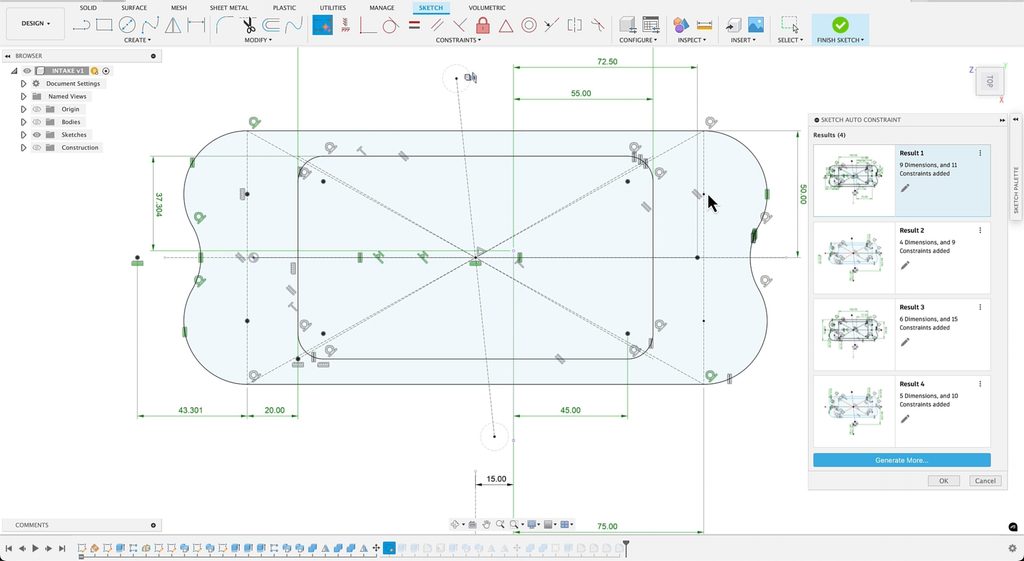
One notable addition in the September 2026 update is Finish Sketch with AutoConstrain.
This option automatically applies sketch constraints after a sketch is finished, helping users create more robust and fully constrained sketches.
Another useful improvement is the ability to identify under-constrained sketch geometry.
Rather than manually searching through complex sketches, users can identify geometry that still requires constraints or dimensions.
These developments address an important engineering challenge: a model should not only look correct in its current state but should also behave predictably when modified.
For professional product development, this distinction is particularly important when models are shared between designers, engineering teams, and manufacturing departments.
6. From Individual Components to Configurable Product Families
Modern product development frequently involves multiple versions of the same component.
Automotive brackets, industrial enclosures, machine components, and consumer products may need different dimensions or mounting configurations depending on customer requirements.
Creating separate models for every variation can introduce unnecessary duplication and increase maintenance effort.
Parametric modeling provides an alternative.
By using named parameters, configurations, and associative relationships, engineers can create a common design framework that supports multiple product variations.
For example, a family of mounting brackets could use parameters controlling:
- Overall length.
- Material thickness.
- Mounting-hole spacing.
- Hole diameter.
- Rib dimensions.
- Clearance requirements.
Instead of rebuilding each version independently, designers can manage different configurations through a common model structure.
This approach can improve design consistency and make engineering changes easier to control.
It is particularly useful for companies producing configurable products or maintaining large component libraries.
7. Connecting CAD with Manufacturing and Product Data
Parametric modeling becomes even more valuable when design information is connected to downstream engineering activities.
Autodesk Fusion combines design, simulation, manufacturing, electronics, technical drawings, and data management within a connected platform.
The September 2026 update introduced several improvements that strengthen these connections.
Product Manufacturing Information (PMI)
Fusion added capabilities for creating and editing manufacturing information directly within the Design workspace.
Hole and thread annotations can include information such as diameter, depth, tolerances, and thread specifications.
PMI can also be used in downstream manufacturing and inspection workflows.
STEP AP242 Support
The September update also expanded PMI-related workflows, while the October update added STEP AP242 export support for PMI data.
This is relevant because STEP AP242 provides a standardised way of exchanging product manufacturing information alongside 3D geometry.
Assembly Performance
Large and complex assemblies remain a major challenge for CAD software.
Autodesk’s October 2026 update introduced performance improvements for large, nested assemblies, including reported gains of up to 35% in opening, saving, and editing performance under the tested conditions.
These improvements are particularly relevant to engineers working with complex product structures and multi-component assemblies.
Together, these capabilities demonstrate that modern CAD development is increasingly focused on maintaining useful engineering information throughout the product lifecycle.
8. The Role of Parametric Modeling in CAD/CAM/CAE Integration
The relationship between CAD, CAM, and CAE is becoming increasingly important as engineering workflows become more connected.
A well-structured parametric model can provide a more reliable starting point for downstream engineering activities.
CAD – Design and Geometry Management
Parametric CAD defines component geometry, dimensions, constraints, assemblies, and design relationships.
When requirements change, the model can be updated through its parameters and feature history.
CAE – Simulation and Engineering Validation
Updated geometry can be used in structural analysis, thermal simulation, vibration studies, and other engineering evaluations.
However, a geometrically valid CAD update does not automatically guarantee that the simulation model remains valid. Meshes, contacts, boundary conditions, and material assumptions may require additional review.
CAM – Manufacturing Preparation
The updated design can also be transferred to manufacturing workflows for CNC programming, toolpath generation, and machining simulation.
Changes to geometry may require manufacturing setups and toolpaths to be reviewed or regenerated.
This is why preserving design intent is important beyond the modelling environment itself.
It helps engineers manage changes more systematically across the product development process.
9. Limitations and Engineering Considerations
Despite its advantages, parametric modeling is not automatically the best solution for every design task.
Complex feature dependencies can make models difficult to maintain if they are not structured carefully.
Poorly defined constraints may create unexpected behaviour when dimensions change.
Imported geometry can require additional preparation before feature recognition or parametric reconstruction becomes practical.
Direct modeling may be more efficient for certain conceptual modifications or imported components where the original design history is unavailable.
AI-assisted reconstruction also introduces another consideration: recognised features must be reviewed before being treated as reliable engineering information.
Engineers remain responsible for validating geometry, dimensions, tolerances, material requirements, and functional performance.
The objective is not to eliminate engineering judgement but to reduce repetitive work and make design information easier to manage.
10. The Future of Parametric CAD: From Geometry Creation to Engineering Intelligence
The evolution of Autodesk Fusion reflects a broader transformation across the CAD industry.
Traditional CAD software focused primarily on creating and modifying accurate digital geometry.
Modern engineering platforms are increasingly expected to understand relationships, preserve design logic, automate repetitive operations, and connect product information across multiple disciplines.
AI-assisted feature recognition could become particularly valuable in environments where engineers work with large libraries of legacy components and supplier models.
Intent-driven design can help organisations create more adaptable product families.
Connected CAD/CAM/CAE workflows can reduce the effort required to transfer design changes between engineering and manufacturing activities.
However, the real progress will not be measured only by the number of automated commands or new modelling tools.
It will depend on whether these technologies help engineers make better decisions, reduce unnecessary reconstruction, and maintain reliable product information throughout the lifecycle.
The CAD Verse Editorial Perspective
Autodesk Fusion’s recent developments demonstrate how parametric modeling is evolving from a geometry-focused methodology into a more comprehensive engineering approach.
The combination of design intent, feature history, user parameters, direct editing, and AI-assisted reconstruction addresses one of the most persistent challenges in product development: managing design changes without losing the logic behind the original model.
AutoTimeline is particularly interesting because it targets a long-standing limitation of CAD interoperability.
Imported geometry has traditionally been easier to view and measure than to modify intelligently. AI-assisted feature reconstruction could make existing CAD data more useful by providing a faster route towards editable parametric models.
At the same time, the continued development of sketch automation, assembly performance, PMI, and manufacturing integration shows that CAD software is increasingly expected to support the complete product development process.
The future of parametric modeling will not be defined simply by how quickly engineers can create 3D geometry. It will be defined by how intelligently software can preserve design intent, understand existing models, and support engineering decisions throughout the product lifecycle.
References