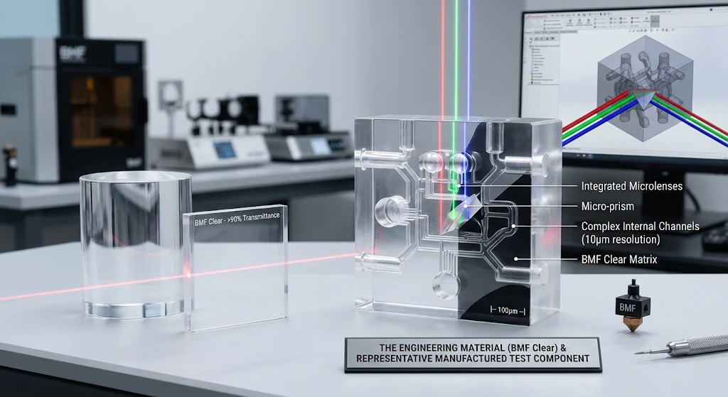
Boston Micro Fabrication has introduced BMF Clear, a transparent photopolymer intended for micro-scale components requiring both fine geometry and optical access. The company reports light transmittance above 90% and compatibility with its 10-micron and 25-micron printing systems, with layer heights between 10 and 50 microns. The announcement points towards microfluidics, photonics and miniature optical features. For a designer, the important development is the possibility of combining internal geometry and a useful optical path within one manufactured component.
Transparency is an application requirement
A clear material can be useful when an engineer needs to observe fluid movement or transmit light through a miniature feature. However, a transmittance percentage requires context before it becomes a design input. Wavelength, specimen thickness and surface condition can influence the result. The announcement’s headline figure should therefore be followed by a request for the relevant test conditions and material documentation.
The geometry of the actual part also matters. A simple test specimen and a long internal channel do not necessarily present the same optical path. Reflections, surface texture and the direction from which the feature is observed can affect visibility. Designers should identify what must be seen or transmitted and create an evaluation geometry that represents that requirement. Visual transparency alone does not establish suitability for a quantitative optical measurement.
Fine features need an accessible process route
Micro-scale additive manufacturing can create complex arrangements without assembling many separate pieces, but it also introduces practical questions about removing uncured material and cleaning internal passages. A channel that exists correctly in CAD still needs to emerge as an open, usable feature. Access points, passage layout and the inspection strategy should be considered while the design is being developed.
The same applies to features intended to align fibres or support optical interfaces. Small dimensional errors can affect an alignment function even when the surrounding part appears satisfactory. The drawing should identify those critical relationships and the method used to verify them. Nominal printer resolution is a useful technology descriptor, but it is not a substitute for the demonstrated capability of a specific feature and orientation.
Integration can remove assembly steps
BMF describes opportunities to combine fluidic passages and optical features within printed structures. Such integration may reduce the number of separate interfaces, but it can also make a defect harder to isolate or repair. The engineering comparison should account for both effects. A consolidated component may be attractive when repeated alignment is difficult, while a modular design may remain useful where replacement or adjustment is important.
Prototype evaluation should consequently include the complete intended function. A clear passage used for visual observation, an optical coupling feature and a window for analytical equipment involve different acceptance criteria. Testing one does not establish the others. The team should select the most important function first, define measurable requirements and then decide whether the manufacturing approach provides sufficient repeatability.
Treat material evidence with appropriate boundaries
The supplier also reports biocompatibility testing in selected categories. Those statements describe material test evidence and should not be expanded into a general approval of any finished medical device. A complete device has its own geometry, processing history and intended use. Engineering and regulatory teams must establish what evidence applies to the actual product, rather than transferring the claim without review.
BMF Clear’s value will depend on the combination of optical behaviour, dimensional performance and a workable cleaning process in the intended design. For The CAD Verse readers, the announcement is a useful invitation to reconsider miniature assemblies that have been difficult to manufacture conventionally. The next step is a representative functional sample, supported by documented material conditions and an inspection plan matched to the real optical or fluidic task.
Source — dailycadcam.com. Source publication date 2026-04-13. Engineering analysis: The CAD Verse.